Difference between revisions of "Picorder 2"
Directive0 (Talk | contribs) (→CPU) |
Directive0 (Talk | contribs) (→PCBs) |
||
| (7 intermediate revisions by the same user not shown) | |||
| Line 1: | Line 1: | ||
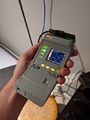
| − | [[File:Unit00 and unit01 20210929.jpg|thumb|The current prototype test rigs Unit 00 (left) and Unit 01 (right)]] | + | [[File:Unit00 and unit01 20210929.jpg|thumb|The current prototype test rigs Unit 00 (left) and Unit 01 (right)]] |
| Line 9: | Line 9: | ||
<span style="color:#008000">Latest update:</span> | <span style="color:#008000">Latest update:</span> | ||
| − | Prototype 01 is now | + | Prototype 01 is now complete. Unit 02 construction is now underway. |
<span style="color:#ff0000">To Do:</span> | <span style="color:#ff0000">To Do:</span> | ||
| − | - | + | -Unit 02 Assembly. |
| − | + | ||
| Line 33: | Line 32: | ||
* [https://www.tindie.com/products/pkawas/tiny-ups-30-tiny-sized-ups-for-usb-devices/ Tiny Ups 3.0] or [https://www.aliexpress.com/item/1005001315194333.html comparable DC-DC boost module]. | * [https://www.tindie.com/products/pkawas/tiny-ups-30-tiny-sized-ups-for-usb-devices/ Tiny Ups 3.0] or [https://www.aliexpress.com/item/1005001315194333.html comparable DC-DC boost module]. | ||
* [https://www.pishop.ca/product/lithium-ion-polymer-battery-3-7v-1000mah/ 1000 mAh Lithium Ion Polymer Battery] | * [https://www.pishop.ca/product/lithium-ion-polymer-battery-3-7v-1000mah/ 1000 mAh Lithium Ion Polymer Battery] | ||
| + | |||
===Prototype Units=== | ===Prototype Units=== | ||
| Line 39: | Line 39: | ||
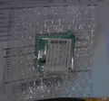
File: Prototype 20201017.jpg| An initial "proof of concept" build. Using the first revision of the custom mainboard pcb as well as several off-the-shelf breakout boards from adafruit. Sensor board was a pi-hat protoboard with adafruit sensor breakouts. Unit 00 also served as a test bed for shift register controlled lighting, sticker fit and finish, and printed light diffusers. This prototype utilized a development sensor array and cap and was not indicative of the final version. Construction of this prototype is considered "complete". | File: Prototype 20201017.jpg| An initial "proof of concept" build. Using the first revision of the custom mainboard pcb as well as several off-the-shelf breakout boards from adafruit. Sensor board was a pi-hat protoboard with adafruit sensor breakouts. Unit 00 also served as a test bed for shift register controlled lighting, sticker fit and finish, and printed light diffusers. This prototype utilized a development sensor array and cap and was not indicative of the final version. Construction of this prototype is considered "complete". | ||
</gallery> | </gallery> | ||
| + | |||
====Unit 01==== | ====Unit 01==== | ||
| Line 44: | Line 45: | ||
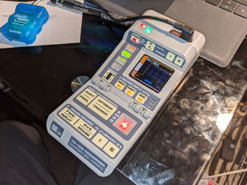
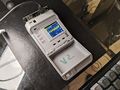
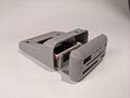
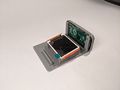
File:Unit01-210929.jpg| This "production" prototype is being used to iron out the remaining problems with integrated systems and hardware. It features a revision 3 mainboard and sensorboard PCB. Unit 01 employs a new case design that attempts to more accurately capture the shape of the Tr-590 Mark VI Tricorder. The case changes are completely superficial and no changes have been made to the underlaying chassis-rail system. Early chassis designs will still work with this new enclosure. | File:Unit01-210929.jpg| This "production" prototype is being used to iron out the remaining problems with integrated systems and hardware. It features a revision 3 mainboard and sensorboard PCB. Unit 01 employs a new case design that attempts to more accurately capture the shape of the Tr-590 Mark VI Tricorder. The case changes are completely superficial and no changes have been made to the underlaying chassis-rail system. Early chassis designs will still work with this new enclosure. | ||
</gallery> | </gallery> | ||
| + | |||
====Unit 02==== | ====Unit 02==== | ||
| − | + | <gallery widths=500px heights=400px> | |
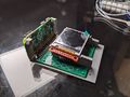
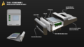
| + | File:TR109-02-SHELL-ASSEMBLY.jpg| Unit 02 is a further refinement in what I learned in Unit 01. It will incorporate the same basic electronics packages, but use new tweaks to the case. I will use the oppourtunity to streamline the assembly process and make any final adjustments. | ||
| + | </gallery> | ||
| + | ===PCBs=== | ||
| + | Custom PCBs were designed for the project. KiCAD files are available at the [https://github.com/directive0/TR-109/tree/main/pcb_design github page]. | ||
| + | {| class="wikitable" style="margin:auto" | ||
| + | |+ Main Board Pinout | ||
| + | |- | ||
| + | ! BCM Pin !! IC Pin !! TR109 Device | ||
| + | |- | ||
| + | | 0 || 27 || CAP1208 Event Ready Pin | ||
| + | |- | ||
| + | | 1 || 28 || Unused | ||
| + | |- | ||
| + | | 2 || 3 || I2C SDA | ||
| + | |- | ||
| + | | 3 || 5 || I2C SCL | ||
| + | |- | ||
| + | | 4 || 7 || Hall Effect Sensor 2 | ||
| + | |- | ||
| + | | 5 || 29 || Power Status GPIO | ||
| + | |- | ||
| + | | 6 || 31 || Mainboard Shift Register Latch | ||
| + | |- | ||
| + | | 7 || 26 || Unused | ||
| + | |- | ||
| + | | 8 || 24 || Screen (CS) | ||
| + | |- | ||
| + | | 9 || 21 || Unused | ||
| + | |- | ||
| + | | 10 || 19 || Screen (SDA) | ||
| + | |- | ||
| + | | 11 || 23 || Screen (SCK) | ||
| + | |- | ||
| + | | 12 || 32 || Hall Effect Sensor 1 | ||
| + | |- | ||
| + | | 13 || 33 || Audio Out | ||
| + | |- | ||
| + | | 14 || 8 || Unused | ||
| + | |- | ||
| + | | 15 || 10 || Screen (LED) | ||
| + | |- | ||
| + | | 16 || 36 || Shift Register Serial | ||
| + | |- | ||
| + | | 17 || 11 || GPIO Button 1 | ||
| + | |- | ||
| + | | 18 || 12 || PocketGeiger (Noise) | ||
| + | |- | ||
| + | | 19 || 35 || Sensor Board Shift Register Serial | ||
| + | |- | ||
| + | | 20 || 38 || Main Board Shift Register Clock | ||
| + | |- | ||
| + | | 21 || 40 || Sensor Board Shift Register Latch | ||
| + | |- | ||
| + | | 22 || 14 || GPIO Button 3 | ||
| + | |- | ||
| + | | 23 || 16 || Screen (AO) | ||
| + | |- | ||
| + | | 24 || 18 || Screen (RESET) | ||
| + | |- | ||
| + | | 25 || 22 || PocketGeiger (Signal) | ||
| + | |- | ||
| + | | 26 || 37 || Sensor Board Shift Register Clock | ||
| + | |- | ||
| + | | 27 || 13 || GPIO Button 2 | ||
| − | + | |} | |
| − | + | ||
====MainBoard==== | ====MainBoard==== | ||
The Main Board hosts all the control electronics for capacitive touch, LED indication (operator facing), door close hall effect sensors, and graphical and audio output. | The Main Board hosts all the control electronics for capacitive touch, LED indication (operator facing), door close hall effect sensors, and graphical and audio output. | ||
| + | |||
| + | Capacative touch is provided by a CAP1208 capacitive touch sensor, LED operation is driven by an 8-bit Shift Register, Bipolar Hall Effect sensors are used for the door state detection. Audio is not yet finalized, and so an external audio connection can be bodged. | ||
<gallery widths=500px heights=400px> | <gallery widths=500px heights=400px> | ||
| Line 62: | Line 129: | ||
</gallery> | </gallery> | ||
| + | |||
====SensorBoard==== | ====SensorBoard==== | ||
| Line 71: | Line 139: | ||
</gallery> | </gallery> | ||
| − | |||
===CPU=== | ===CPU=== | ||
| Line 86: | Line 153: | ||
The intention of the Picorder project is to create a device that can accept any arbitrary sensor arrangement and map it (assuming the appropriate software has been written to support it). But the TR109 PCBs and case is planned to be capable of supporting 3 main sensor packages on it forward facing array: | The intention of the Picorder project is to create a device that can accept any arbitrary sensor arrangement and map it (assuming the appropriate software has been written to support it). But the TR109 PCBs and case is planned to be capable of supporting 3 main sensor packages on it forward facing array: | ||
| − | ;[https://www.bosch-sensortec.com/products/environmental-sensors/gas-sensors/bme680/ | + | ;[https://www.bosch-sensortec.com/products/environmental-sensors/gas-sensors/bme680/ BME680 VOC, Temp, Humidity, Pressure sensor] |
: The BME680 is a basic environmental sensor. VOC is a nice added feature that adds some real world use, but interpreting the reading requires some analysis. This sensor will mostly be to provide ambient environmental information. For prototyping I found a good [https://learn.adafruit.com/adafruit-bme680-humidity-temperature-barometic-pressure-voc-gas/python-circuitpython guide] for how to connect it to a Pi and used Adafruits circuitpython library to integrate it into [[PicorderOS]]. Because the BME680 includes 4 seperate data sources in one device I am making it the "base model" sensor for this project. I will direct most of my efforts to make the best experience when using this sensor. | : The BME680 is a basic environmental sensor. VOC is a nice added feature that adds some real world use, but interpreting the reading requires some analysis. This sensor will mostly be to provide ambient environmental information. For prototyping I found a good [https://learn.adafruit.com/adafruit-bme680-humidity-temperature-barometic-pressure-voc-gas/python-circuitpython guide] for how to connect it to a Pi and used Adafruits circuitpython library to integrate it into [[PicorderOS]]. Because the BME680 includes 4 seperate data sources in one device I am making it the "base model" sensor for this project. I will direct most of my efforts to make the best experience when using this sensor. | ||
| Line 162: | Line 229: | ||
====Video Updates==== | ====Video Updates==== | ||
I've been releasing update videos to catalogue my progess. | I've been releasing update videos to catalogue my progess. | ||
| + | |||
| + | |||
| + | {{#evt: | ||
| + | service=youtube | ||
| + | |id=https://youtu.be/FyRxHhpjpfk | ||
| + | |container=frame|alignment=inline | ||
| + | }} | ||
| + | |||
{{#evt: | {{#evt: | ||
| Line 179: | Line 254: | ||
<gallery> | <gallery> | ||
| + | File:Tr1090 cappads.jpg | Unit 02's possible Cap Pad assembly before soldering. | ||
File:Rev2sensorboard20210331.jpg| Revision 2 sensor board backside | File:Rev2sensorboard20210331.jpg| Revision 2 sensor board backside | ||
File:Unit01 sensorboard 20210331.jpg | Revision 2 sensor board with full LED compliment installed. Bodge wires are visible on the hc595 shift register (missing pull up/down pin pads). No sensors have been tested on this board yet. | File:Unit01 sensorboard 20210331.jpg | Revision 2 sensor board with full LED compliment installed. Bodge wires are visible on the hc595 shift register (missing pull up/down pin pads). No sensors have been tested on this board yet. | ||
Latest revision as of 20:30, 16 March 2024

The TR-109 Picorder 2 project aims to develop and produce a portable, self contained, Raspberry Pi based sensor data acquisition platform in the shape of a Tricorder.
It is the successor to the original Picorder. Originally the projects goal was to make a single Tricorder replica, but the Picorder 2 project has slowly lead to a set of standards for the Picorder family of devices I want to make.
Latest update:
Prototype 01 is now complete. Unit 02 construction is now underway.
To Do:
-Unit 02 Assembly.
Contents
Software
Picorder 2 uses PicorderOS a python library that unifies a number of different modules under a custom user interface.
Hardware
Downloads
All of the TR-109's build files are freely available and hosted at the Git repo.
Basic Parts List
While more info can be found below, a basic list of all the off the shelf (not including PCB components) parts is:
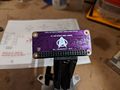
- Raspberry Pi Zero W or drop-in-compatible SBC
- St7735 Screen
- Stemma Speaker Module
- Tiny Ups 3.0 or comparable DC-DC boost module.
- 1000 mAh Lithium Ion Polymer Battery
Prototype Units
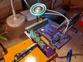
Unit 00
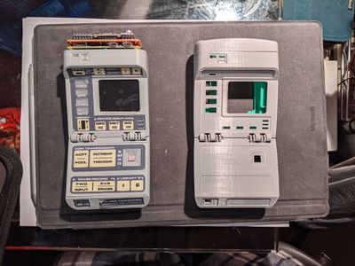
An initial "proof of concept" build. Using the first revision of the custom mainboard pcb as well as several off-the-shelf breakout boards from adafruit. Sensor board was a pi-hat protoboard with adafruit sensor breakouts. Unit 00 also served as a test bed for shift register controlled lighting, sticker fit and finish, and printed light diffusers. This prototype utilized a development sensor array and cap and was not indicative of the final version. Construction of this prototype is considered "complete".

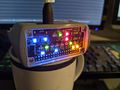
Unit 01
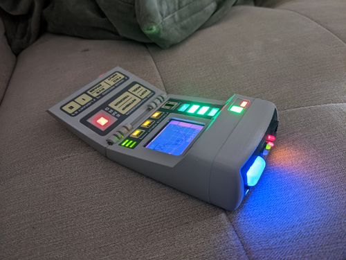
This "production" prototype is being used to iron out the remaining problems with integrated systems and hardware. It features a revision 3 mainboard and sensorboard PCB. Unit 01 employs a new case design that attempts to more accurately capture the shape of the Tr-590 Mark VI Tricorder. The case changes are completely superficial and no changes have been made to the underlaying chassis-rail system. Early chassis designs will still work with this new enclosure.

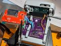
Unit 02
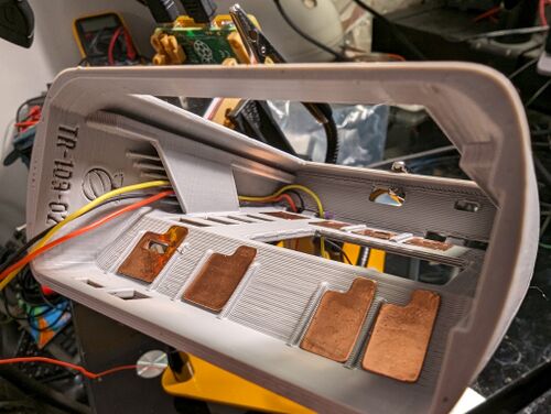
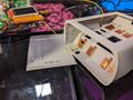
Unit 02 is a further refinement in what I learned in Unit 01. It will incorporate the same basic electronics packages, but use new tweaks to the case. I will use the oppourtunity to streamline the assembly process and make any final adjustments.

PCBs
Custom PCBs were designed for the project. KiCAD files are available at the github page.
| BCM Pin | IC Pin | TR109 Device |
|---|---|---|
| 0 | 27 | CAP1208 Event Ready Pin |
| 1 | 28 | Unused |
| 2 | 3 | I2C SDA |
| 3 | 5 | I2C SCL |
| 4 | 7 | Hall Effect Sensor 2 |
| 5 | 29 | Power Status GPIO |
| 6 | 31 | Mainboard Shift Register Latch |
| 7 | 26 | Unused |
| 8 | 24 | Screen (CS) |
| 9 | 21 | Unused |
| 10 | 19 | Screen (SDA) |
| 11 | 23 | Screen (SCK) |
| 12 | 32 | Hall Effect Sensor 1 |
| 13 | 33 | Audio Out |
| 14 | 8 | Unused |
| 15 | 10 | Screen (LED) |
| 16 | 36 | Shift Register Serial |
| 17 | 11 | GPIO Button 1 |
| 18 | 12 | PocketGeiger (Noise) |
| 19 | 35 | Sensor Board Shift Register Serial |
| 20 | 38 | Main Board Shift Register Clock |
| 21 | 40 | Sensor Board Shift Register Latch |
| 22 | 14 | GPIO Button 3 |
| 23 | 16 | Screen (AO) |
| 24 | 18 | Screen (RESET) |
| 25 | 22 | PocketGeiger (Signal) |
| 26 | 37 | Sensor Board Shift Register Clock |
| 27 | 13 | GPIO Button 2 |
MainBoard
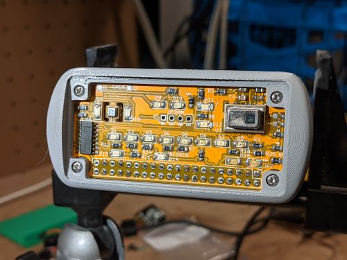
The Main Board hosts all the control electronics for capacitive touch, LED indication (operator facing), door close hall effect sensors, and graphical and audio output.
Capacative touch is provided by a CAP1208 capacitive touch sensor, LED operation is driven by an 8-bit Shift Register, Bipolar Hall Effect sensors are used for the door state detection. Audio is not yet finalized, and so an external audio connection can be bodged.
Unit 01 with Rev 3 mainboard exposed and peripheral boards.

SensorBoard
The Sensor Board hosts all the control electronics for LED indicators (forward facing) as well as any sensors that the device will address.
Revision 3 sensor board with full LED and sensor compliment installed.

CPU
The TR-109 is designed to use a:
- Raspberry Pi Zero W
- I have found a really good article on some ways to reduce power consumption.
- BPI-M2 Zero
- The quad core Banana Pi M2 Zero is a great candidate for this project, offering multiple cores and more ram. But the practicality of using a BPI has proven a problem. The BPI uses a custom Raspbian distro that needs seperate GPIO modules and has different setup requirements.
Sensors
The intention of the Picorder project is to create a device that can accept any arbitrary sensor arrangement and map it (assuming the appropriate software has been written to support it). But the TR109 PCBs and case is planned to be capable of supporting 3 main sensor packages on it forward facing array:
- BME680 VOC, Temp, Humidity, Pressure sensor
- The BME680 is a basic environmental sensor. VOC is a nice added feature that adds some real world use, but interpreting the reading requires some analysis. This sensor will mostly be to provide ambient environmental information. For prototyping I found a good guide for how to connect it to a Pi and used Adafruits circuitpython library to integrate it into PicorderOS. Because the BME680 includes 4 seperate data sources in one device I am making it the "base model" sensor for this project. I will direct most of my efforts to make the best experience when using this sensor.
- AMG8833 IR Thermal Camera
- The AMG8833 is a relatively low resolution and low range thermal camera. It will basically only be useful for detecting dramatic temperature difference. It is also relatively cheap and so I am going to include it. This sensor will provide quasi-accurate contextual temperature information at range.
- MLX90614 Non Contact Thermometer
- A cheap and accessible non contact thermometer. This sensor provides accurate specific temperature readings at range. I've managed to find Adafruits own circuitpython implementation and this page looks fruitful too.
Other Options
Other possible sensor options include
- MiCS6814
- I was turned onto the idea of an 8 gas sensor by the ODROID-GO Ticorder project where they used this IC to measure carbon minoxide, nitrogen dioxide, hydrogen, ammonia, methane, propane, and iso-butane. I found a great blogpost on some ways to use it. Because it is an analog sensor I would need to use an ADC and some way to connect it to the Pi.
- An EMF sensor of some kind.
- Probably a resistor on an ADC to give me basic environmental electrical readings. I found this site that shows you how you can use at AT tiny as an i2c device, which I could use with this guide to make a small EMF detector to read low frequency interference. Another option suggested to me by reddit user 2CNK is to use an Elektrosluch like device to convert ambient EMI into some kind of data. I found a circuit example that might prove useful.
Audio
Audio is provided by a Stemma Speaker Module for now, but I hope to have audio integrated into the mainboard.
Shell
The TR-109 is designed to use a custom made 3D printed enclosure. The STLs are available at the Git repo.

|

|
General Design
New shell (right) will be used for Prototype Unit 01.

Recently I redesigned the shell on the Picorder to use a more accurate style of enclosure
The current design of the Picorder 2 shell incorporates a main body and chassis with a lower door. All of the major components are housed in the main body with the lower door being used for extra buttons and battery storage. The mainboard PCB is attached to the chassis, along with the Raspberry Pi, the sensor board and all internal lighting. The chassis slides in and out of the main body on tracks, and is secured to the main body with 4 M2 screws.
Custom printed stickers are used for the labeled button areas.
Input
- CAP1208 Capacitive Touch Sensor IC
- Originally I was going to use the MPR121, I found a good guide on how to use it, but since the chip is discontinued I decided to look for other options. I became interested in a chip I saw mentioned in the documentation for a pimoroni product; the CAP1208.
- The chip includes a number of features like hold detection, and has an interrupt pin. The entire CAP1xxx series is supported by a library maintained by Pimoroni and I have been pleased with its performance.
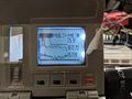
Display

- Generic ST7735 LCD Display
- I've been using screens with of this type with the Luma.lcd python module. I bet you could also use FBTFT to use it as a display target (requires additional software modifications, but makes it usable as a small computer). The display I found (pictured) had no pins listed as MOSI or MISO (for SPI) but I found a pin chart in the Luma docs that helped.
- I found this was a decent source for these screens.
I had considered the idea of also supporting a low cost screen, but the availability is poor.:

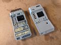
- Nokia 5110 LCD screen
- To provide low power information output to the user, and maybe to play some snake. I looked in a number of places to find a good guide on how to connect the Adafruit part I have with various descriptions around the web. I found this guide to have some important information, but the wiring information seemed incorrect. This guide lays out how to connect the screen properly..
LEDS
As with the original picorder I want to make sure that this one has a feel of the actual prop. The LEDs on the TR-109 are designed to be as faithful as possible to the original Mark Vii prop as possible, while making some compromises for layout and electronic constraints.
The LEDs on the sensor board and the light riser board are entirely SMD, but on the main board the ABGD lights are 3mm Green LEDS.
Power
Umbilical power as supplied by the Raspberry Pi Zero W's onboard USB port.
Portable power is stored by a 1000 mAh Lithium Ion Polymer Battery. Power can then regulated by an Alchemy Power Tiny-UPS. As an alternative I recommend something like a J5019 DC-DC Boost Module.
Video Updates
I've been releasing update videos to catalogue my progess.
Gallery
Unit 02's possible Cap Pad assembly before soldering.
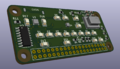
Revision 2 sensor board backside
Revision 2 sensor board with full LED compliment installed. Bodge wires are visible on the hc595 shift register (missing pull up/down pin pads). No sensors have been tested on this board yet.
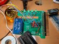
The revision 2 mainboard with integrated capacitive touch, shift register LED driver and on board single transistor audio amplifier.
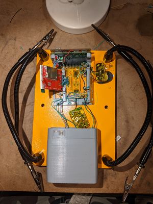
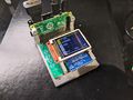
The prototype chassis holds the rev 2 mainboard which connects to the display, supports the interface elements, hall effect sensors, and main indicator LEDs.

Unit 01 front panel in early development (March 2021)
Unit 00 and Unit 01 in early development (March 2021)
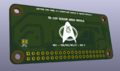
KiCad render of the backside of the revision 2 sensor board PCB design showing off its beautiful livery
KiCad render of the frontside of the revision 2 sensor board PCB, showing off it's single side of SMD components.
The Picorder 2 revision 1 main board prototype showing off some new modifications that will be part of revision 2.
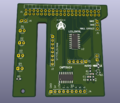
The frontside of the Rev 2 main board PCB design showing off its beautiful livery
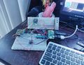
The Picorder 2 prototype, August 2020
The Picorder 2 prototype, March 2020
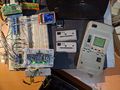
The Picorder 2 test platform, March 2020

The Picorder 2 test platform, March 2020
The Picorder 2 test platform, March 2020
On March 4th 2020 I received word the first prototype boards were being shipped out.
The Picorder 2 test platform, February 2020
The Picorder 2 test platform, February 2020
General 3d printed plan
The Picorder 2 test platform, Nov 2019
Older prototype
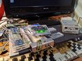
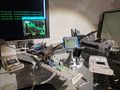
Major components being tested
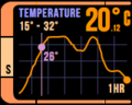
Example thermal cam output
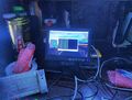
Actual Dot Matrix UI Being Tested
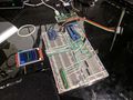
Picorder 2 Laid Out on Breadboard
Picorder 2 laid out on breadboard with dual displays.
PicorderOS LCARS mockup


Media Coverage
I'm delighted that my project has been noticed by some online publications
- Raspberry Pi Tricorder: The Next Generation - Ian Evenden, Tom's Hardware
- "TR-109 RASPBERRY PICORDER 2 REALLY NAILS THE STAR TREK AESTHETIC" - Lewin Day, Hackaday
This project is a "MyCorder" build and so I'm using Discord to communicate directly with fellow builders and this subreddit to solicit advice from the community.