Difference between revisions of "Picorder 2"
Directive0 (Talk | contribs) (→Display) |
Directive0 (Talk | contribs) (→Software) |
||
| Line 71: | Line 71: | ||
===Software=== | ===Software=== | ||
| − | New software will be written that runs on some of the basic concepts of the original Picorder program. | + | New software will be written that runs on some of the basic concepts of the original Picorder program. In some cases it will not use Pygame though, which could provide considerable performance and power savings, hopefully. |
====Notes==== | ====Notes==== | ||
Revision as of 08:13, 20 June 2019

This page serves as a repository of information I have collected as I acquire sensors and materials for my successor to the original Picorder. What began as wanting to make a single Tricorder replica is slowly becoming more of a set of standards for the picorder family of devices I want to make.
Contents
Sensing Goals
Basic ambient environmental; temperature, pressure, humidity and VOC (Volatile Organic Compounds). Ranged line-of-sight temperature sensing (very small envelope. 0°c to 80°c). Magnetometer, maybe something like spectroscope if I can find one that works. Electromagnetic interference of a very arbitrary envelope could be displayed using some kind of ADC and an antenna.
CPU
- Raspberry Pi Zero W
- My old favourite will return for this model. Power consumption was a MAJOR problem with the first Picorder, I have found a really good article on some ways to reduce power consumption. I am playing with the idea of using something like an arduino or just an ATTINY, but the Pi has so many advantages.
Shell
There are some options:
- Mark 7 Tricorder Replica
- I've acquired a prop replica kit for the mark 7 tricorder from Stapleton Productions.
- 1993 Playmates Tricorder Toy
- For the prototype, this is easy to get and modify.
Input
- MPR121 Capacitive Touch Buttons
- Controller to use small metal pads for capacitive buttons for inputs. I found a good guide and software info for the Pi here.
Display
There are two main display targets for this project.
The first is a low cost low power monochrome screen:

- Nokia 5110 LCD screen
- To provide low power information output to the user, and maybe to play some snake. I looked in a number of places to find a good guide on how to connect the Adafruit part I have with various descriptions around the web. I found this guide to have some important information, but the wiring information seemed incorrect. This guide lays out how to connect the screen properly..
And for my second prototype I will use this colour screen.

- Generic ST7735 LCD Display
- In applications where power isn't as critical a screen like this can provide full colour rich interface. Use of this screen can be facilitated by specifically pushing data to this screen using the Luma python module (more work but perhaps less processor intensive) or by using FBTFT to use it as a display target (requires additional software modifications, but allows for generic computing functions to be displayed). The display I found (pictured) had no pins listed as MOSI or MISO (for SPI) but I found a pin chart in the Luma docs that helped.
Sensors
- Bm860 VOC, Temp, Humidity, Pressure sensor
- The BME680 is a basic environmental sensor. VOC is a nice added feature. This sensor will provide ambient environmental information. I've found a good guide for how to connect it to a Pi.
- AMG8833 IR Thermal Camera
- This is a VERY low resolution and low range thermal camera. It will basically only be useful for detecting dramatic temperature differences. It was relatively cheap so I want to include it. This sensor will provide inaccurate CONTEXTUAL temperature information at range.
- MLX90614 Non Contact Thermometer
- A cheap and accessible non contact thermometer. This sensor provides accurate specific temperature readings at range. This page looks fruitful.
- An EMF sensor of some kind.
- Probably a resistor on an ADC to give me basic environmental electrical readings. I found this site that shows you how you can use at AT tiny as an i2c device, which I could use with this guide to make a small EMF detector to read low frequency interference.
LEDS
As with the original picorder I want to make sure that this one has a feel of the actual prop. the TOS tricorder only had 3 indicator lights but the TNG tricorder is lit up like a christmas tree.
I'm going to try and include at the very least:
- the four green indicator lights (alpha, beta, delta, gamma)
- the front panel sensor array (the green ripple lights, the various and sundry sensor illuminations)
- the EMRG button
- the PWR button.
- GEO, MET, BIO buttons.
ALPHA BETA DELTA GAMMA
Its always perplexed me that these indicator lights seem to ripple (light up and turn off one after the other) in different directions depending on the season of TNG you're watching.
It makes sense to me that the LEDs on the Tricorder should ripple from top to bottom (alpha to gamma).
I have read (somewhere) that the TNG Tricorder lights were changed by a prop maker to run in the opposite direction only so they could tell when their work was being used on screen.
Controller
I think in the interest of reducing processing load on the Pi I will just use the Pi as a clock and pulse a GPIO pin high and low to a number of decade counters to control the "look and feel" LEDS.
Software
New software will be written that runs on some of the basic concepts of the original Picorder program. In some cases it will not use Pygame though, which could provide considerable performance and power savings, hopefully.
Notes
To reduce power consumption:
- Only draw to screen when sensor reading has changed.
scale would be a factor for determining; different decimal places would trigger different refresh rates.
Download
https://github.com/directive0/picorder2
Installation
PicorderOS requires quite a few python libraries to work.
Open a terminal and follow the next instructions:
- We must first enable SPI and I2C for sensor and display communications.
- Open Raspi Config
sudo raspi-config - Select "Interfacing Options" (Item 5)
- Scroll down to SPI and when prompted enable it following the onscreen dialogue
- Do the same for I2C
- Open Raspi Config
- Ensure you have Python3 and Pip3 installed (should already be there on Raspbian)
sudo apt-get install python3-pip python3-dev - Install Sensor Libraries
- If using the BME680 I recommend the Pimoroni bme680 module, install it using pip3
sudo pip3 install bme680
- If using the BME680 I recommend the Pimoroni bme680 module, install it using pip3
- Install luma.lcd for the displays
sudo pip3 install luma.lcd
User Interface
Picorder 2 will us PicorderOS and so there are a number of display options available now. More info to follow.
I have given some thought to how I want the device to be usable by the operator. I'm hoping to make as many functional buttons as possible, but its difficult to determine what the best course is. For the meantime I've made this rough design for a standard bar graph readout. This style of information display seems congruent with the LCARS interface seen in the show.

Gallery
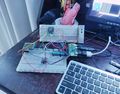
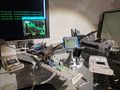
Major components being tested
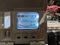
Example thermal cam output
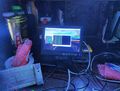
Actual Dot Matrix UI Being Tested
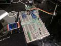
Picorder 2 Laid Out on Breadboard
Picorder 2 laid out on breadboard with dual displays.


MyCorder
This project is a "MyCorder" build and so I'm using this subreddit to solicit advice from the community.